Repairing a 3 way Slide Rest for a WW Lathe
Copyright 2008 by James
P. Riser
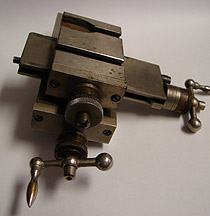
 This is the condition in which the slide rest was found
and purchased. It was too nice to just let sit in a junk drawer.
Slide rests with such damage will often show up on used equipment
sites so I thought others might be interested in seeing how I
salvaged this example.
Here are a few close-ups of the damaged section. The
brown stuff is old shellac.
This is the condition in which the slide rest was found
and purchased. It was too nice to just let sit in a junk drawer.
Slide rests with such damage will often show up on used equipment
sites so I thought others might be interested in seeing how I
salvaged this example.
Here are a few close-ups of the damaged section. The
brown stuff is old shellac.


 The first thing I did was to tighten up all of the
gib screws and swivel lock so that the parts would not shift during
the necessary machining. The complete slide rest was placed in
the vise of my Burke #4 milling machine for the required work.
Everything was carefully lined up prior to any cutting.
The first thing I did was to tighten up all of the
gib screws and swivel lock so that the parts would not shift during
the necessary machining. The complete slide rest was placed in
the vise of my Burke #4 milling machine for the required work.
Everything was carefully lined up prior to any cutting.
 Front and rear
views ...
Front and rear
views ...  To prevent unnecessary rotational forces on the swivel
portion of the slide, I selected a slitting saw for cutting. Being
rather thin, it would not impart unwanted forces on the slide.
Below is a series of images made during the machining.
To prevent unnecessary rotational forces on the swivel
portion of the slide, I selected a slitting saw for cutting. Being
rather thin, it would not impart unwanted forces on the slide.
Below is a series of images made during the machining.


 The plan was to replace the damaged and missing parts
with .065" hard brass strips.
The plan was to replace the damaged and missing parts
with .065" hard brass strips.
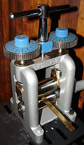
 The brass strip was sheared at the factory which left
a burr on the bottom surface edges and a slightly rounded top
surface. To counteract this and make the heavy brass flat, I decided
to roll it in one of my rolling mills. This did the job beautifully.
The brass strip was cut to length on the Burke milling
machine.
The brass strip was sheared at the factory which left
a burr on the bottom surface edges and a slightly rounded top
surface. To counteract this and make the heavy brass flat, I decided
to roll it in one of my rolling mills. This did the job beautifully.
The brass strip was cut to length on the Burke milling
machine. 
 Here is a test
fit of the brass pieces.
Here is a test
fit of the brass pieces.  My plan was to attach these brass pieces to the top
slide using J-B Weld. The J-B Weld was to hold the brass in place
while I drilled and tapped the strips and top slide to more fully
attach the strips and better hold the strips in place. The brass
strips will be held in place by 4-40 machine screws for the desired
strength.
My plan was to attach these brass pieces to the top
slide using J-B Weld. The J-B Weld was to hold the brass in place
while I drilled and tapped the strips and top slide to more fully
attach the strips and better hold the strips in place. The brass
strips will be held in place by 4-40 machine screws for the desired
strength.
 A thin layer of
J-B Weld was applied to the right machined area.
The brass strip was laid into position and a 1/4"
aluminum spacer piece was laid next to the brass strip.
A thin layer of
J-B Weld was applied to the right machined area.
The brass strip was laid into position and a 1/4"
aluminum spacer piece was laid next to the brass strip.
 J-B Weld was applied to the left side or end portion
of the top slide.
J-B Weld was applied to the left side or end portion
of the top slide. 
 The second brass
piece was set into position.
The aluminum spacer was removed leaving the two parallel
brass strips in their correct positions.
The second brass
piece was set into position.
The aluminum spacer was removed leaving the two parallel
brass strips in their correct positions.

 Another view ...
  The J-B Weld was left to cure for a full 24 hours before
doing the drilling and tapping for the screws.
The next step was to remove the top slide.
The J-B Weld was left to cure for a full 24 hours before
doing the drilling and tapping for the screws.
The next step was to remove the top slide.  The hole positions were laid out and I wanted to avoid
punching the hole positions with a center punch.
The hole positions were laid out and I wanted to avoid
punching the hole positions with a center punch.
 This is the spotting
drill used to "punch" the marked holes.
This is the spotting
drill used to "punch" the marked holes.
 The holes "spotted"
and ready for drilling.
The holes "spotted"
and ready for drilling. 
 The holes were
tapped, counter sunk, and ss screws inserted.
The holes were
tapped, counter sunk, and ss screws inserted.  The stainless steel
screw sockets were ground off flush.
The stainless steel
screw sockets were ground off flush.  Here is the final result. The slide is now stronger
than it was originally and is ready to earn its keep.
Here is the final result. The slide is now stronger
than it was originally and is ready to earn its keep.
 Another view...
 I'm pleased with this little repair job.