Adding a Crosshair
to the
Student Grade Premiere Microscope
Copyright 2002 by James P. Riser
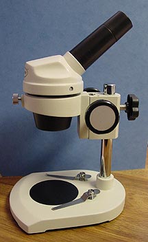
 I purchased
this student grade 20x microscope to assist in indexing cutting
tools on my EMCO Compact 5 PC Lathe. The microscope is inexpensive
and once a crosshair is added will serve this purpose quite well.
Premiere Microscopes does not supply a crosshair for this scope
so one must be fabricated.
A crosshair must be made from
an extremely thin filament which is also very strong. In the past
the web from a black widow spider has been used for this task.
Since I live in Tucson, Arizona, finding an accommodating black
widow would be easy. Before I went looking for the spider and
her web, I remembered that I had a spool of Kevlar thread on hand
and figured that I could unravel it to get a single fine filament.
Shown at the right is a short length of this thread after unravelling.
You can see the individual fibers.
I purchased
this student grade 20x microscope to assist in indexing cutting
tools on my EMCO Compact 5 PC Lathe. The microscope is inexpensive
and once a crosshair is added will serve this purpose quite well.
Premiere Microscopes does not supply a crosshair for this scope
so one must be fabricated.
A crosshair must be made from
an extremely thin filament which is also very strong. In the past
the web from a black widow spider has been used for this task.
Since I live in Tucson, Arizona, finding an accommodating black
widow would be easy. Before I went looking for the spider and
her web, I remembered that I had a spool of Kevlar thread on hand
and figured that I could unravel it to get a single fine filament.
Shown at the right is a short length of this thread after unravelling.
You can see the individual fibers.
 The easily removable eyepiece
has the standard recess built into it. It is into the bottom of
this recess that the crosshair must be placed. On a better grade
of microscope the eyepiece tube will be threaded to adjust the
lens spacing and to add the crosshair fitting. If the crosshair
is not in the correct focal plane, it will be out of focus.
The easily removable eyepiece
has the standard recess built into it. It is into the bottom of
this recess that the crosshair must be placed. On a better grade
of microscope the eyepiece tube will be threaded to adjust the
lens spacing and to add the crosshair fitting. If the crosshair
is not in the correct focal plane, it will be out of focus.
 Before machining the crosshair
fitting, I decided to do a quick and dirty test of the Kevlar
filament and of the assumed focal plane.
In the image at the right you
can see a single filament stretched across the bottom of the recess.
It is temporarily held in position with tape. When I looked through
the eyepiece, I could see that everything was in focus and would,
indeed, work as desired.
The next step was to machine
a mounting ring for the crosshair.
Before machining the crosshair
fitting, I decided to do a quick and dirty test of the Kevlar
filament and of the assumed focal plane.
In the image at the right you
can see a single filament stretched across the bottom of the recess.
It is temporarily held in position with tape. When I looked through
the eyepiece, I could see that everything was in focus and would,
indeed, work as desired.
The next step was to machine
a mounting ring for the crosshair.
 I
chose to machine the plastic fitting on my watchmaker's lathe.
The setup is shown here.
I
chose to machine the plastic fitting on my watchmaker's lathe.
The setup is shown here.
 A 3/8" long section of heavy
walled PVC plastic tubing was the basis for the fitting. Here
you can see it mounted in the lathe chuck ready to have the cut
end squared off.
A 3/8" long section of heavy
walled PVC plastic tubing was the basis for the fitting. Here
you can see it mounted in the lathe chuck ready to have the cut
end squared off.
 After squaring the end, the slide
rest was rotated to zero so that a square shoulder could be cut
on the plastic.
After squaring the end, the slide
rest was rotated to zero so that a square shoulder could be cut
on the plastic.
 The worst part of this whole
project is the fine strands of plastic which are removed. They
static cling to everything!
The worst part of this whole
project is the fine strands of plastic which are removed. They
static cling to everything!
 The
shoulder should be square like this.
It is a good idea to make certain
that the turned shoulder fits the eyepiece tube.
The
shoulder should be square like this.
It is a good idea to make certain
that the turned shoulder fits the eyepiece tube. 

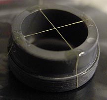
 I next reversed the fitting in
the chuck to machine the other end so that it would align properly
with the end of the eyepiece tube.
Shown here are the finished fitting
and an extra piece of PVC tubing.
I next reversed the fitting in
the chuck to machine the other end so that it would align properly
with the end of the eyepiece tube.
Shown here are the finished fitting
and an extra piece of PVC tubing. 
The next step was to add the
Kevlar filaments to this fitting. Things get pretty difficult
to see during this process and the microscope can be used to make
the job easier. I covered the black plexiglass microscope base
plate with thin plastic wrap to protect it while attaching the
filaments. Super glue was used as the glue for attaching the Kevlar
strands to the plastic ring. You do not want to get this on the
black plexiglass!
 These images illusttrate the
attaching of the crosshair filaments.
The fibers were held stretched
until the glue set.
Instead of Kevlar fibers, single
strands from nylon panty hose could be used.
These images illusttrate the
attaching of the crosshair filaments.
The fibers were held stretched
until the glue set.
Instead of Kevlar fibers, single
strands from nylon panty hose could be used.
Below are images showing the
modified microscope in use.
The crosshairs. 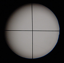
 Indexing
a tool.
Indexing
a tool.
I mounted the whole microscope
assembly onto a magnetic indicator base to temporarily attach
it to the lathe bed while indexing tools on my EMCO lathe.
The magnetic base came from Harbor
Freight and the post was slightly smaller that the original microscope
post. A brass bushing was made to take up the "slack".
 This bushing was made from three
different diameters of thin walled brass tubing as found in hobby
and hardware stores.
The tubing lengths were soldered
together. Notice that the largest diameter tubing forms a collar
on the bushing.
The wall of the bushing was slotted
in four places to allow it to collapse as the microscope clamping
knob is tightened.
To do this job correctly, I should
have machined the bushing from solid brass bar and slotted it
on my milling machine rather than free hand.
I was lazy today! It works.
This bushing was made from three
different diameters of thin walled brass tubing as found in hobby
and hardware stores.
The tubing lengths were soldered
together. Notice that the largest diameter tubing forms a collar
on the bushing.
The wall of the bushing was slotted
in four places to allow it to collapse as the microscope clamping
knob is tightened.
To do this job correctly, I should
have machined the bushing from solid brass bar and slotted it
on my milling machine rather than free hand.
I was lazy today! It works.
 The
bushing was then slid onto the magnetic base post - collar down.
The scope was slid down onto
the post around this bushing and the knob tightened.
The
bushing was then slid onto the magnetic base post - collar down.
The scope was slid down onto
the post around this bushing and the knob tightened. 
 Here
is the complete setup - ready to mount on the lathe bed.
I hope this web page will help
others who are trying to machine metal and plastics on a limited
budget. Enjoy.
Here
is the complete setup - ready to mount on the lathe bed.
I hope this web page will help
others who are trying to machine metal and plastics on a limited
budget. Enjoy.